

FAQ
- How do I identify the different AiRSensors systems?
- Are the Mass Air Flow sensors interchangeable between the AiRSensors analog and digital systems?
- Can the AirSensors throttle body be used in other applications, such as, a system without an Air Mass Sensor, or with a different style injector?
- Does the AirSensors ECU control spark timing?
- What is the purpose of the inductive pickup?
- What is the purpose of the temperature sensor?
- How can I test my temperature sensor?
- What would happen if an analog temperature sensor were switched with a digital sensor?
- What is the normal operating pressure for the AirSensors fuel system?
- Can the fuel delivery system have good pressure, but still have a bad pump?
- What fuel pump does the AirSensors EFI use?
- How do I calibrate the ANALOG ECU (no gas analyzer)?
- How do I calibrate the ANALOG ECU (chassis dyno)?
- How do I do a road test after calibrating my Analog ECU?
- How do I calibrate the F.I.R.S.T. DECU (chassis dyno)?
- How do I calibrate the F.I.R.S.T. DECU (no gas analyzer)?
- How do I do a road test after calibrating my DECU?
- What type injector and impedance is the AiRSensors N-8A analog or F.I.R.S.T. digital ECU designed for?
- How do I wire a fuel pump relay?
- How is the analog wiring harness configured?
- Do AirSensors EFI systems have a CARB number, that is, qualify for exemption under Section 27156 of CARB (California Air Resources Board) Vehicle Code?
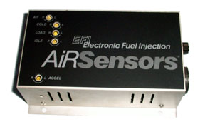
How do I identify the different AiRSensors systems?
|
|
Analog ECU, N-8A
|

|
|
Analog ECU, N-8A-HD
|

|
|
Analog ECU Superjection
|
|
|
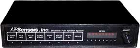
Digital ECU
|
AiRSensors, Inc. was one of the first after-market fuel injection companies, and they offered a very well designed system based on analog electronics, and featuring a Mass Air Flow sensor as the primary input. Although it was a simple system, unsophisticated by today's standards, it is nevertheless a robust design and thousands are still in service. By calibrating the various control parameters it could drive 4, 6, 8, or more cylinders, with boost added by turbo or blower, at various horsepower ratings. With a four-injector throttle body, the most common configuration, it can be thought of as an adjustable electronic carburetor. Other suppliers eventually offered systems based on AiRSensors products, with B&M's Superjection blower kit being the most well known.
After the initial successes of the analog designs, AiRSensors began to offer systems based on digital technology, and developed various intake manifolds under the F.I.R.S.T. brand name. Other suppliers offered systems based on AiRSensors F.I.R.S.T. products, Clifford Performance and their Jeep kits being the most well known. Using a Mass Air Flow sensor again, as the primary input, F.I.R.S.T. systems began to appear on the market and become recognized as viable designs at about the time that the AiRSensors, Inc. group dissolved and slipped into oblivion.
The most common analog ECUs encountered today are model N-8A or N-8A-HD and B&M Superjection versions. They are about the size of a common bread loaf pan, black or aluminum finished with screwdriver adjustable controls on the top. The -HD version may have a large finned heat sink attached underneath.
F.I.R.S.T. digital ECUs are thin and flat, painted black, with red LEDs, membrane pushbutton switches and a single adjustment control on the front panel.
Are the Mass Air Flow sensors interchangeable between the AiRSensors analog and digital systems?
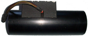
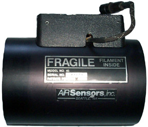
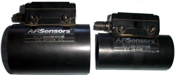
No. Although AiRSensors produced 3", 4", and 5" MAF sensors that look similar externally, they will not interchange between analog and digital applications. The internal hotwire bridge circuitry is similar, but the outputs are different. The analog MAF
|
|
Analog MAF, 3 in.
|
|
|
Analog MAF, 4 in.
|
|
|
Digital MAF, 3 and 4 in.
|
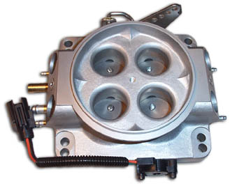
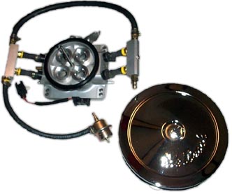
Can the AirSensors throttle body be used in other applications, such as, a system without an Air Mass Sensor, or with a different style injector?
 |
| Throttle body with top-fed injectors and air cleaner |
Yes, the AirSensors-style throttle body was once marketed by ACCEL in a speed-density based fuel injection system that used top-fed injectors. Fuel rails and cross-over tubes were used in place of hoses and barbed injectors. It had a Throttle Position Sensor (TPS), Idle Air Control (IAC), and an air cleaner in place of the plenum and intake filter.
 |
| Throttle body with TPS, IAC, fuel rails |
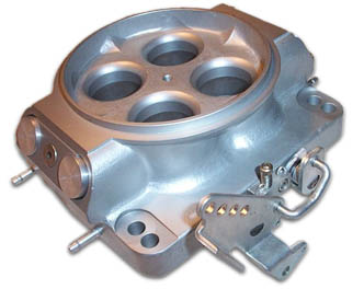 |
| Throttle Body with Plugs |
An AMS was not needed.
The use of a throttle body as an air gate (air valve), without the original injectors is also commonly done. Plugs are used in place of injectors.
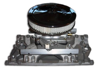 |
| Air Gate on MPI Manifold |
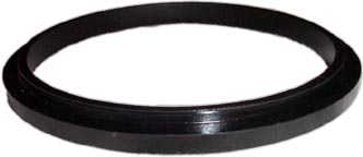 |
| Filter Adapter Ring |
The Analog throttle body has neither TPS nor IAC but each can be added with some machining and adapter parts. The plenum can be replaced with many commonly available after-market air filters by using an adapter ring that steps up the t-body's top of 4.80" to the more common 5.125" (5-1/8").
 |
| Throttle body with TPS |
 |
| Throttle body with reducers |
Though the throttle body flows in excess of 750 cfm, it can be sleeved down to smaller flow rates by the use of reducer adapters. And it can be bored out to greater than 1000 cfm if desired.
Does the AiRSensors ECU control spark timing?
No. The AirSensors ECU and F.I.R.S.T. DECU only control the fuel delivery, and not spark timing. The spark timing can be controlled independently by most original and aftermarket distributor systems, including Points-types, Capacitive Discharge, HEI, MSD, etc.
The green tach wire from the ECU should be connected to the negative (-) terminal of the coil, if a conventional points-type distributor or coil is used, or to the (Tach) terminal on an HEI- type. The wiring harness includes an imbedded resistor in the green tach lead, (4700 ohm for analog system, 8200 ohm for the digital system) which should be present for correct operation.
When using an MSD-type system the resistor in series with the green tach wire inside the harness must be removed, and the wire lengthened and insulated if necessary. Connect the green wire to the (Tach) terminal on the MSD ignition box.
What is the purpose of the inductive pickup?
The inductive pickup is used to time the injectors to the engine's firing order on throttle body (single point) units only, especially those with dual-plane manifolds. They are not necessary for Multi-point or Tuned Port engines, and may not be necessary for turbocharged, supercharged or engines with single-plane manifolds.

|
|
Inductive pickup
|
For G.M., Chrysler, AMC, IHC engines with firing order 18436572, the pickup is referenced to cylinder #6.
For Fords with firing order 15426378, use cylinder #5 for reference.
For Fords with firing order 13726548, use cylinder #3 for reference.
The pickup is used to smooth the engine running, especially at idle to below 1500 RPM. Experimenting with other cylinder references may improve running.
What is the purpose of the temperature sensor?
The temperature sensor is installed to monitor the warm-up of the engine, signaling to the ECU or DECU that the cold enrichment (choke) is no longer needed. It is a temperature sensitive resistor imbedded in a battery cable lug, with wiring to interconnect. If it is installed in an inappropriate location, the performance and fuel economy may suffer. For most installations, the intake manifold, under the second bolt from the rear may be the best location. In cold climates, with the radiator fan blowing across the sensor, it may never feel operating temperature and fail to signal the ECU to turn off cold enrichment. In such a situation, the better location may be behind a cylinder head, out of the air stream. In all cases, it should never be located over an exhaust gas port or runner.
How can I test my temperature sensor?
As mentioned previously, suitable location of the temperature sensor on the engine is critical to its function. Once proper placement has been verified, it is a simple matter of verifying the sensor's resistance relative to ambient temperature. Analog and Digital System temperature sensors differ in their composition, and are therefore not interchangeable. The test procedure, however, is the same for both. The procedure is as follows:
- Disconnect the harness from the ECU.
- Refer to the wiring harness pin-out diagram furnished in the manual, or in this FAQ section.
- For Analog ECU:
- Note that pin 16 references the temperature sensor.
- Note that pin 22 references the battery ground (-).
- Measure the resistance, pin 16 to pin 22.
- For Digital ECU:
- Note that pin 4 references the temperature sensor.
- Note that pin 1 references the battery ground (-).
- Measure the resistance, pin 4 to pin 1.
- For Analog ECU:
- At an assumed ambient temperature of 75ºF, (25ºC) the resistance of the sensor (analog or digital) should be 10k to 20k ohms.
- This test verifies the sensor and wiring.
- Resistance substantially different from expected may indicate a bad sensor or wiring problem.
Temperature sensors can also be tested at temperatures other than ambient (75ºF) if one knows the correct resistance. For instance, boiling water is always at 212ºF, and ice water is close to 32ºF, (freezing). Use one or both of these reference points to test temperature sensors.
Analog Temperature Sensor Degrees (F) Resistance (Ohms) 32 2.8 k 77 16.0 k 185 225.0 k 212 350.0 k Digital Temperature Sensor Degrees (F) Resistance (Ohms) 32 32.7 k 77 10.9 k 185 1.1 k 212 .7 k
What would happen if an analog temperature sensor were switched with a digital sensor?
If a temperature sensor meant for Analog computer use were switched with a Digital type, or vice versa, the results would be the same: the engine would be hard to start while cold due to extreme lean fuel conditions. The ECU would call for reduced fuel instead of enrichment (choke) as would be needed for cold start. After warm-up, the system would run very rich, and performance and economy would suffer.
For identification purposes the Analog sensor has two black wires, while the Digital sensor has one black and one gray wire.
What is the normal operating pressure for the AirSensors fuel system?
AirSensors used fuel pressure regulators rated at 39 psi with their standard horsepower systems, and often used regulators of 55 psi with their high horsepower options. All are in-line mounted with hose barbed inlets and outlets. The 39 psi regulator has a 5/16" inlet and outlet while some of the 55 psi regulators have inlets of 3/8" and outlets of 1/4". It is highly recommended that the return line to the tank should be 3/8", or a minimum of 5/16", to keep the pressure low (less than 1 psi). If a regulator with a 1/4" outlet barb is in use, it should have 5/16" line installed.
Throttle Body (Single Point Injection) systems have the vacuum reference port on the regulator connected to the intake system Air Plenum through a 3/16" vacuum hose. Presumably, the intent is to protect against high-pressure fuel leakage in the engine compartment in event of a ruptured regulator diaphragm.
This effectively references the regulator to atmospheric pressure, maintaining a constant fuel pressure under all conditions. Some adjustable regulators with no vacuum reference have been observed also.
Tuned Port (TPI), Multi-point (MPI), supercharged or turbo-boosted engines always have their regulator vacuum reference connected to a manifold vacuum port. This allows for constant pressure differential across the injectors as the manifold vacuum changes, and the pressure regulator adjusts correspondingly.
Can the fuel delivery system have good pressure, but still have a bad pump?
Yes, the pressure only tells part of the story. A fuel pressure gauge can display the correct psi, and mislead one into looking elsewhere for the cause of poor performance. Most fuel injection pumps are pushers, and do not have much suction power. That is why they are mounted lower than the tank for gravity assistance, or inside the fuel tank, and may have a primary pump to boost the fuel. If a filter or hose has an obstruction, or diminished fuel flow, the pump can still build pressure but not flow adequate volume to feed a thirsty engine.
The fuel delivery system consists of the tank selector valve, pump or pumps, filters, hoses, rails, injectors, regulator and tank. The regulator sets the system pressure, while the pump provides volume, or flow. All unused fuel must return to the tank.
To test for adequate flow we must measure the output of the fuel system, (the return side), for a period of time, in addition to testing the pressure.
Try this ballpark test. (The intent is to measure the un-loaded fuel flow. We want to verify that the system can supply enough fuel flow with the engine off).
- Get a scale that can weigh at least 10 lbs. and a container of at least 1-½ gallon capacity. Weigh the empty container and record empty weight. Alternatively, get a 1-½ gallon container with graduated markings to measure volume.
- Get a hose (5/16” or 3/8”) long enough to carry fuel from the return side of the fuel regulator to the container, and a hose clamp. (Or, better yet, we could use the return hose detached at the tank end. This will check the return hose for restrictions).
- Locate the fuel pump relay or other pump power point, and provide +12 volts to run the pumps. A “Hotwire” from the battery is okay.
- With pump turned off, remove the return-side hose from the regulator and attach the test hose and clamp. (Or remove the return hose from the tank end). Place other end into empty container.
- Provide +12 volts to the pump for exactly 60 seconds and shut off pump.
- Weigh the container of fuel and subtract the weight of the empty container. This is the weight of the fuel delivered in one minute. Alternatively, measure the volume of fuel and convert to gallons if necessary.
- Referring to the lookup table, determine what the theoretical system flow should be for the engine’s estimated horsepower, for one minute.
Naturally Aspirated Engine - Fuel Factor = .5 Max H/P (Wide Open Throttle) Fuel-Lbs/Hr. Fuel-Gal/Hr. Fuel-Lbs/Min Fuel-Gal/Min 100 50 8.33 0.83 0.14 150 75 12.50 1.25 0.21 200 100 16.67 1.67 0.28 250 125 20.83 2.08 0.35 300 150 25.00 2.50 0.42 350 175 29.17 2.92 0.49 400 200 33.33 3.33 0.56 450 225 37.50 3.75 0.63 500 250 41.67 4.17 0.69 550 275 45.83 4.58 0.76 600 300 50.00 5.00 0.83 650 325 54.17 5.42 0.90 700 350 58.33 5.83 0.97 750 375 62.50 6.25 1.04 800 400 66.67 6.67 1.11 Boosted Engine - Fuel Factor = .6 Max H/P (Wide Open Throttle) Fuel-Lbs/Hr. Fuel-Gal/Hr. Fuel-Lbs/Min Fuel-Gal/Min 100 60 10.00 1.00 0.17 150 90 15.00 1.50 0.25 200 120 20.00 2.00 0.33 250 150 25.00 2.50 0.42 300 180 30.00 3.00 0.50 350 210 35.00 3.50 0.58 400 240 40.00 4.00 0.67 450 270 45.00 4.50 0.75 500 300 50.00 5.00 0.83 550 330 55.00 5.50 0.92 600 360 60.00 6.00 1.00 650 390 65.00 6.50 1.08 700 420 70.00 7.00 1.17 750 450 75.00 7.50 1.25 800 480 80.00 8.00 1.33 - Restore everything to the original condition, and begin looking for the flow obstruction if the measured values are 10-20% less than the theoretical values.
Remember, also, that long runs of small gage wire to the pump, or low voltage at the pump can cause low fuel flow. Pumps that have been allowed to run dry may be damaged and unable to provide adequate flow. For more information, see How do I wire a fuel pump relay?.
What fuel pump does the AirSensors EFI use?
AirSensors fuel injection systems commonly used electric fuel pumps manufactured by Walbro. They were designed for either in-tank or in-line mounting, with inlets of 1/2" (12mm) and outlets of 3/8". Models 5530 and 532 were the most common; however, both models are no longer in production. Running at system pressures of nominally 39 psi or 55 psi, they were designed to provide fuel flow adequate for the horsepower ratings of the engines they fed, measured in gallons per hour. Several fuel pumps commonly available today from different manufacturers can replace the Walbro, if the demands of the engine are satisfied.
To determine the required fuel pump specifications, use this formula for a ball-park guide:
Maximum fuel consumption = 0.5 lb gasoline/hp/hour (at wide open throttle)
Weight of fuel = 6 lbs gasoline/gallon, System pressure = 39 psi
Example:
| 400 hp x 0.5 lb gas/hp/hr = | 200 lb gas/hr 6 lbs gas/gal |
= 33.33 gal/hr |
Turbo boosted or supercharged engines should be run richer; use 0.6 lb gas/hp/hr
Example:
| 400 hp x 0.6 lb gas/hp/hr = | 240 lb gas/hr 6 lbs gas/gal |
= 40.0 gal/hr |
Based on the first example you would look for a pump which flows at least 33 gal/hr at 39 psi. Using a pump with greater pressure or fuel flow specifications is acceptable.
ECU CALIBRATION PROCEDURE
NO GAS ANALYZER (RPM ADJUSTMENT)
Before beginning, ensure that the engine is in good condition: no vacuum leaks, good compression, good fuel pressure (39psi), ignition timing correct, etc.
- In general, follow these tuning guides:
- Always ensure that the engine is up to operating temperature before attempting to adjust anything, other than "Cold Mix".
- "A/F" adjusts the main Air/Fuel ratio, everything else is based on this one setting. Once it is adjusted, leave it alone and only make minor adjustments later.
- Allow several seconds after an adjustment, for system stabilization, before reaching any conclusions about the efficacy of your changes.
- Adjust only one parameter at a time, to allow verification of the effects of the change.
- Idle setting is done last, due to a small interaction with the other adjustments.
- Cold setting is done with the engine, cold, of course!
- The factory presets (11 o'clock on all pots) is a good starting point and should get the engine up and running. If difficulty is experienced in reaching the desired tuning, reset the pots to 11 o'clock, and begin again.
CW and CCW are Clock Wise and Counter Clock Wise.
- Start engine and bring to full operating temperature; transmission in neutral. Connect tachometer to observe engine rpm.
- Set throttle body speed screw, or hold throttle pedal down, to obtain steady 2,200 rpm.
- While maintaining throttle position, and turning A/F pot, adjust cruise mix to full rich position (CW). You should notice a decrease in engine rpm. Now adjust cruise mix to full lean position (CCW). You should notice an increase, then a decrease in engine rpm. Once you have verified rpm, both rich and lean, set for maximum engine rpm (usually somewhat into rich side).
- Set throttle body idle speed screw for desired idle rpm, i.e. 800 in neutral, (standard transmission) 700 in drive (for automatic transmission).
- Adjust IDLE pot for smoothest idle at engine rpm from step #4
Caution: The next step must be performed with great care so as not to have a runaway vehicle! Chocking wheels is a good idea.
- For vehicles with automatic transmission:
Apply brakes and place transmission in Drive (to apply load to engine). Bring up engine to above 2300 rpm. Adjust LOAD pot for best relative power. (Power sag or ping indicates too lean; black exhaust smoke indicates too rich). Return engine to idle.
For vehicles with manual transmission:
Adjust LOAD pot CCW. Load setting must be done under load (hard to do with a manual transmission in gear with brakes on!). LOAD setting will be determined during road test.
- With engine at idle, and transmission in neutral, adjust ACCEL pot to set acceleration pulse by stabbing the throttle and noting the engine response. The goal is to adjust-out bogs or hesitation during quick acceleration. Remember, a too rich condition can cause a bog also.
- Set COLD mix next day, (while engine is cold) for smooth cold idle.
YOU ARE NOW READY FOR A ROAD TEST!
ECU CALIBRATION PROCEDURE
CHASSIS DYNO W/ GAS ANALYZER
Before beginning, ensure that the engine is in good condition: no vacuum leaks, good compression, good fuel pressure (39psi), ignition timing correct, etc.
NOTES: Adjustments should be made in small increments, followed by a wait of several seconds to verify the effect of the change, before another adjustment is made. Assure the vehicle is secured from moving while making standing adjustments.
- Disable air pump. All gas samples are taken with air pump disabled and before catalytic converter.
- With engine fully warm, no load, set RPM to 2500 and adjust A/F to about .8-1% CO reading for exhaust.
- Run vehicle up to freeway speed in high gear. Load dyno to anticipated load factor: i.e. 15 hp for passenger car, 25 hp for trucks, 35 hp for motor homes.
- At near full throttle adjust LOAD to 4-5% CO for exhaust.
- At idle, in gear, set throttle body idle speed screw for desired idle rpm, i.e. 800 in neutral, (standard transmission) 700 in drive (for automatic transmission).
- At idle adjust IDLE control for factory CO% level, approximately 2-3 CO% @700 rpm in drive or 800 in neutral with standard transmission. Should this result in a rough idle, re-adjust for smoothest idle and set desired RPM with throttle body idle speed screw.
- Re-check cruise mix at no load, 2500 RPM. Adjust if necessary to less than 1% CO for exhaust.
- Adjust ACCEL for a peak reading of 8% CO on a quick acceleration run on dyno from a dead stop to full throttle. Make several quick acceleration runs to check for hesitation or stumble off idle, adjusting ACCEL as necessary to provide smooth accelerations. Return engine to idle.
- Restore air pump operation and plug catalytic converter access hole.
- Set COLD MIX next day, (while engine is cold) for smooth cold idle.
YOU ARE NOW READY TO DRIVE!
ANALOG ECU CALIBRATION PROCEDURE
ROAD TEST
NOTES: CW and CCW are Clock Wise and Counter Clock Wise. For safety, always have a passenger to make the ECU adjustments.
-
ROAD TEST
- Drive far enough to ensure that the engine is up to operating temperature.
- Cruise at normal road speed, level highway, to set the A/F level. (The pre-sets should be close, so don't make major adjustments). Set it between "stumbling" and "smooth" running, or using O2 meter, around 14.7 (midrange).
- Set LOAD to begin enrichment at some point above the cruise setting of above step. (Improper LOAD setting can cause poor fuel economy and lack of power). Begin to hard accelerate, or climb a hill or on-ramp, to see how the engine pulls. If it is slow to respond, or lacks power, adjust LOAD pot and make minor adjustments (CW to increase richness). With an O2 meter, set mixture somewhere around 12-13, or richer (higher on the scale) than cruise. After repeated accelerations to feel the response, adjust LOAD, if necessary, to the best setting above cruise, so that power is there when you need it, with good fuel economy at cruise. Noticeable black smoke indicates an excessively rich condition.
- Drive in stop and go traffic conditions to set ACCEL. Adjust to cause acceleration to begin from off-idle, without stumbling or hesitation. Black smoke and stumbling may indicate an excessively rich condition: turn ACCEL pot CCW to reduce richness.
- At a stop, make final adjustment to IDLE pot for smoothest idle and highest rpm. Adjust throttle stop screw for correct rpm (700 rpm for automatic transmission, 800 rpm for manual transmission).
DECU CALIBRATION PROCEDURE
CHASSIS DYNO
NOTES: Adjustments must be made within 3-5 seconds once the keypad is pushed, or the command is ignored. L.E.D. is Light Emitting Diode (small red light). CW and CCW are Clock Wise and Counter Clock Wise.
- Disable air pump. All gas samples are taken with air pump disabled and before catalytic converter.
- With engine fully warm, run vehicle up to freeway speed in high gear. If vehicle has overdrive, be sure engine is above 2000 rpm. Load dyno to anticipated load factor: i.e. 15 hp for passenger car, 25 hp for trucks, 35 hp for motor homes.
- Push LOAD START keypad and set ADJUST knob to far right position (CW, L.E.D. #8).
- Push ACCEL START keypad and set ADJUST knob to far right position (CW, L.E.D. #8).
- Push LOAD % keypad and set ADJUST knob to far left position (CCW, L.E.D. #1).
- Push ACCEL % keypad and set ADJUST knob to far left position (CCW, L.E.D. #1).
- Push CRUISE MIX keypad and set ADJUST knob for .80% CO, (some high performance engines may require up to 1.5% CO). Note L.E.D. now lit. Return engine to idle.
- Set throttle body idle speed screw for desired idle rpm, i.e. 800 in neutral, (standard transmission) 700 in drive (for automatic transmission).
- Push IDLE MIX keypad and adjust idle mix for factory CO% level, approximately 2-3 CO% @700 rpm in drive or 800 in neutral with standard transmission.
- Push LOAD START keypad and set ADJUST knob back to L.E.D.#5. Push ACCEL START keypad and set ADJUST knob to back to L.E.D.#5. Run vehicle up to speed and load dyno for full load.
- Push LOAD % keypad and set ADJUST knob for 4-5 CO%. Return engine to idle.
- Push ACCEL % keypad and set ADJUST knob for a peak reading of 8 CO% on a quick acceleration run on dyno from a dead stop to full throttle. Return engine to idle.
- Push LOAD START keypad and set ADJUST knob to two or three L.E.D.s above CRUISE MIX (set in step # 7).
- With engine at idle, push ACCEL START keypad and set ADJUST knob to L.E.D. #3.
- Restore air pump operation.
- Set COLD MIX next day, (while engine is cold) for smooth cold idle.
YOU ARE NOW READY FOR A ROAD TEST!
DECU CALIBRATION PROCEDURE
NO GAS ANALYZER (RPM ADJUSTMENT)
Before beginning, ensure that the engine is in good condition: no vacuum leaks, good compression, good fuel pressure (39psi), ignition timing correct, etc .
In general, follow these tuning guides:
- Always ensure that the engine is up to operating temperature before attempting to adjust anything, other than "Cold Mix".
- "Cruise Mix" is the main Air/Fuel, everything else is based on this one setting. Once it is adjusted, leave it alone and only make minor adjustments later.
- Allow several seconds after an adjustment, for system stabilization, before reaching any conclusions about the efficacy of your changes.
- Adjust only one parameter at a time, to allow verification of the effects of the change.
- Idle setting is done last, due to a small interaction with the other adjustments.
- Cold setting is done with the engine, cold, of course!
- After all the parameters are dialed in, record all the settings for future reference. A "Reset" reverts everything back to factory pre-sets, and you don't want to go through the tuning process again. Just dial all the numbers back in. The settings will be close to original, and are stored when the engine is shut off.
NOTES: Adjustments must be made within 3-5 seconds once the keypad is pushed, or the command is ignored. L.E.D. is Light Emitting Diode (small red light). CW and CCW are Clock Wise and Counter Clock Wise.
- Start engine and bring to full operating temperature; transmission in neutral. Connect tachometer to observe engine rpm.
- Push CRUISE MIX keypad and set ADJUST knob to L.E.D. #5.
- Set throttle body speed screw, or hold throttle pedal down, to obtain steady 2,200 rpm.
- While maintaining throttle position, push CRUISE MIX keypad, and turning ADJUST knob, adjust cruise mix to full rich position (CW, L.E.D. #8). You should notice a decrease in engine rpm.
Now adjust cruise mix to full lean position (CCW, L.E.D. #l). You should notice an increase, then a decrease in engine rpm.
Once you have verified rpm, both rich and lean, set for maximum engine rpm (usually somewhat above lean side). Note L.E.D. now lit.
- Set throttle body idle speed screw for desired idle rpm, i.e. 800 in neutral, (standard transmission) 700 in drive (for automatic transmission).
- Push IDLE MIX keypad and adjust idle mix for smoothest idle at engine rpm from step #5.
- With engine at idle, push LOAD START keypad and set load start to two or three L.E.D.s above CRUISE MIX (set in step # 4).
- With engine at idle, push ACCEL START keypad and set accel start to L.E.D. #3.
- Set all other settings (COLD MIX, LOAD %, ACCEL %) to L.E.D. #5.
- Set COLD MIX next day, (while engine is cold) for smooth cold idle.
YOU ARE NOW READY FOR A ROAD TEST!
DECU CALIBRATION PROCEDURE
ROAD TEST
NOTES: Adjustments must be made within 3-5 seconds once the keypad is pushed, or the command is ignored. L.E.D. is Light Emitting Diode (small red light). CW and CCW are Clock Wise and Counter Clock Wise.
-
ROAD TEST
- Drive far enough to ensure that the engine is up to operating temperature.
- Cruise at normal road speed, level highway, to set the CRUISE MIX. (The pre-sets should be close, so don't make major adjustments). Set it between "stumbling" and "smooth" running, or using O2 meter, around 14.7 (midrange).
- Set LOAD START at 1 or 2 L.E.D. above the CRUISE MIX setting of above step. This will signal the computer to begin the load enrichment at some point above cruise. (Improper LOAD START setting can cause poor fuel economy and lack of power).
Begin to hard accelerate, or climb a hill or on-ramp, to see how the engine pulls. If it is slow to respond, or lacks power, press LOAD % and make minor adjustments (CW to increase richness). With an O2 meter, set mixture somewhere around 12-13, or richer (higher on the scale) than cruise.
Finally, after repeated accelerations to feel the response, adjust LOAD START, if necessary, to the best setting above cruise, so that power is there when you need it, with good fuel economy at cruise. Noticeable black smoke indicates an excessively rich condition.
- Drive in stop and go traffic conditions to set ACCEL START. Adjust to cause acceleration to begin from off-idle, without stumbling or hesitation. Black smoke and stumbling may indicate an excessively rich condition: turn ACCEL % CCW to reduce richness.
- At a stop, make final adjustment to IDLE MIX for smoothest idle and highest rpm. Adjust throttle stop screw for correct rpm (700 rpm for automatic transmission, 800 rpm for manual transmission).
What type injector and impedance is the AiRSensors N-8A analog or F.I.R.S.T. digital ECU designed for?
The N-8A and its derivatives, (Superjection, N-8A-HD etc.) and the F.I.R.S.T digital ECUs each have four injector drivers, designed for low impedance units. Some modified N-8A ECUs had six or eight drivers installed. The majority of these "peak and hold" injectors we have encountered are of a Bosch design, the type used largely by Ford in their two-barrel throttle bodies (5-liter T-Birds, Mustangs, etc.) Typically, they measure 2-4 ohms. After pressing a barbed adapter onto the injectors, a high-pressure hose then top-fed fuel from a fuel rail. Several different flow rates were available: 36 lb. /hr, 46 lb. /hr, 52 lb. /hr, and 80 lb. /hr. have been seen in use. The fuel pressure regulators were set for either 39 or 55 psi.
Though most low impedance drivers today are considered to be peak and hold designs, the AiRSensors analog units appear to be saturated, (while the digital units appear to be a modified peak and hold), when their current waveforms are examined!
What all this means is that an AiRSensors analog or digital ECU can support one low impedance (peak and hold) injector per driver, or at least four high impedance (saturated) 14-17 ohm injectors per driver.
How do I wire a fuel pump relay?
|
|
Fuel pump relay wiring diagram
|
The practice of wiring the fuel pump through an external relay has two objectives:
- To protect the computer from over-current damage. (Some circuit traces inside may burn open if a pump or other component has problems. This is an expensive failure to repair).
- To minimize voltage drop to the fuel pump. (Small gauge wire, switches and/or long runs to the pump may cause a drop in the power needed to run at full output).
Use a Bosch relay 0-332-204-150, or a standard 12V/30 amp. automotive style single pole, double throw with the terminals marked 30, 85, 86, 87, 87a.
- Mount the relay in a suitable place on the firewall. A socket for the relay is okay, or just use push-on terminals.
- Use the red fuel pump wire from the computer to activate the relay through pin 86. Ground pin 85 to the chassis.
- Find a +12V source capable of supplying at least 15 amps, such as a terminal block on the firewall, or even directly to the battery. Install an in-line fuse of 10-15 amps and attach to pin 30 of the relay using 12-10 gage wire.
- Attach a 12-10 gauge wire from pin 87 (the normally open contact) to the (+) terminal of the pump. Ground the pump (-) terminal to the chassis using 12-10 gage wire.
The computer will turn the pump on and off as before, and allow it to run at full power.
See also "Can the fuel delivery system have good pressure, but still have a bad pump?"
Analog Wiring Harness - Leads and Connections

|
|
Figure 2
Analog Injector Connections |
Connect all wire leads as follows:
- Small White - to IGN at the fuse block, to the large red wire on GM HEI distributors or before ballast resistor on point distributors.
- Green - Distributor side of coil, tachometer connection on HEI distributor.
- Gray - Engine Temperature Sensor.
- Violet and Black (with white connector) - to Induction Pick up Sensor.
- Injector Connectors (four) - See Figure 2, right.
- Long Red - to the positive (+) terminal on the fuel pump. (Ground the negative terminal to the frame.)
- Large Black (twisted with large white) - to the negative (-) battery terminal.
- Large White (twisted with large black) - to the positive (+) battery terminal.
- Red (with black ground strap) - to the Optional Fast Idle Air Valve. (Ground to Valve bolt.) Tape off wires if not used.
- Air Mass Sensor Connector - to matching connector on AMS harness. The connection for the air mass sensor is also made before start-up. It must be disconnected to adjust Drive Home as noted below, however, and then reconnected.
Shortening Analog Wiring Harness
Shortening the analog wiring harness is NOT recommended. If shortening is required, DO NOT ELIMINATE or by-pass resistor in the green lead (system will not function).
Injector Connections
The electronically controlled injectors are fired sequentially to optimize cylinder balance and promote smooth idling and best engine performance. The order of firing varies with engine types as noted in Figure 2 above and is particularly important when using a dual plane, 180 degree manifold.
| Analog Plug Pin No. | Wire | Destination | |
| Color | Gauge | ||
| 1 | White | 14 | Battery (+ 12V) |
| 2 | Red | 16 | Fuel Pump (+ 12V) |
| 3 | Red | 16 | All injectors (+ 12V, splits inside harness for red leads to injectors) |
| 4 | Red | 16 | Fast Idle Air Valve (+ 12V) |
| 5 | White | 16 | Air Mass Sensor (Pin #1, +12V) |
| 6 | White | 18 | Switched Ignition (+ 12V) |
| 7 | (Spare) | ||
| 8 | (Spare) | ||
| 9 | Violet | 18 | Induction Pick-up |
| 10 | (Spare) | ||
| 11 | Brown | 18 | Injector #1 (A) |
| 12 | Red | 18 | Injector #2 (B) |
| 13 | Orange | 18 | Injector #3 (C) |
| 14 | Yellow | 18 | Injector #4 (D) |
| 15 | Green | 18 | Coil (negative) Tach signal (4.7K ohms resistor in series within wiring harness cover) |
| 16 | Gray | 18 | Engine Temperature Sensor |
| 17 | Red | 16 | Air Mass Sensor signal (Pin #3) |
| 18 | (Spare) | ||
| 19 | (Spare) | ||
| 20 | (Spare) | ||
| 21 | Black | 16 | Air Mass Sensor ground (Pin #2) |
| 22 | Black | 16 | Battery (Negative) |
Do AirSensors EFI systems have a CARB number, that is, qualify for exemption under Section 27156 of CARB (California Air Resources Board) Vehicle Code?
The AirSensors Analog system with Model N-8A-HD ECU has received Executive Order D-163 (click to view pdf file) for installation on '86 and older GM 454 CID heavy-duty gasoline engines. No other AirSensors system has been exempted by CARB that we know of. Installation of AirSensors systems in any vehicle must comply with applicable State and Federal regulations in force at the time of the vehicle's manufacture and retain any emissions control devices installed by the manufacturer. Vehicles classified as "off road" may be governed by separate regulations. Consult with your State Motor Vehicles Department about local laws.
AiRSensors and F.I.R.S.T. are trademarks of AiRSensors, Inc.
Auto-nomics is not affiliated with AiRSensors, Inc. or its successors.
The information in this web site is freely provided for personal use only, and is not intended for commercial purposes. Auto-nomics assumes no liability for consequences resulting from the use of any information provided here, and makes no claims as to the accuracy or suitability for use. Auto-nomics has sole rights to all print and image content unless otherwise noted.
Last updated on 10/1/11, 12:05 AM